Frequency Reuse Concept In Wireless Communication
The key characteristic of a cellular network is the ability to re-use frequencies to increase both coverage and capacity. As described above, adjacent cells must use different frequencies, however there is no problem with two cells sufficiently far apart operating on the same frequency. The elements that determine frequency reuse are the reuse distance and the reuse factor.
The key characteristic of a cellular network is the ability to re-use frequencies to increase both coverage and capacity. As described above, adjacent cells must use different frequencies, however there is no problem with two cells sufficiently far apart operating on the same frequency. The elements that determine frequency reuse are the reuse distance and the reuse factor.
The reuse distance, D is calculated as

where R is the cell radius and N is the number of cells per cluster. Cells may vary in radius in the ranges (1 km to 30 km). The boundaries of the cells can also overlap between adjacent cells and large cells can be divided into smaller cells.
The frequency reuse factor is the rate at which the same frequency can be used in the network. It is 1/K (or K according to some books) where K is the number of cells which cannot use the same frequencies for transmission. Common values for the frequency reuse factor are 1/3, 1/4, 1/7, 1/9 and 1/12 (or 3, 4, 7, 9 and 12 depending on notation).
In case of N sector antennas on the same base station site, each with different direction, the base station site can serve N different sectors. N is typically 3. A reuse pattern of N/K denotes a further division in frequency among N sector antennas per site. Some current and historical reuse patterns are 3/7 (North American AMPS), 6/4 (Motorola NAMPS), and 3/4 (GSM).
If the total available bandwidth is B, each cell can only use a number of frequency channels corresponding to a bandwidth of B/K, and each sector can use a bandwidth of B/NK.
Code division multiple access-based systems use a wider frequency band to achieve the same rate of transmission as FDMA, but this is compensated for by the ability to use a frequency reuse factor of 1, for example using a reuse pattern of 1/1. In other words, adjacent base station sites use the same frequencies, and the different base stations and users are separated by codes rather than frequencies. While N is shown as 1 in this example, that does not mean the CDMA cell has only one sector, but rather that the entire cell bandwidth is also available to each sector individually.
Depending on the size of the city, a taxi system may not have any frequency-reuse in its own city, but certainly in other nearby cities, the same frequency can be used. In a large city, on the other hand, frequency-reuse could certainly be in use.
Recently also orthogonal frequency-division multiple access based systems such as LTE are being deployed with a frequency reuse of 1. Since such systems do not spread the signal across the frequency band, inter-cell radio resource management is important to coordinate resource allocation between different cell sites and to limit the inter-cell interference. There are various means of Inter-cell Interference Coordination (ICIC) already defined in the standard Coordinated scheduling, multi-site MIMO or multi-site beam forming are other examples for inter-cell radio resource management that might be standardized in the future.

Frequency Reuse Concept


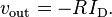
 is the saturation current of the emitter-base diode and
  is the thermal voltage. Due to the virtual ground at the op amp differential input,
 , and
, and

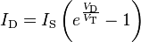
 and the output voltage
  is given by:
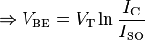
 and
and  are the saturation current and the thermal voltage of the diode respectively.